Concept: IR (Infrared) Sensor
IR (Infrared) Sensor works by emitting infrared signal/radiation and receiving of the signal when the signal bounces back from any obstacle. In other words, the IR Sensor works by continuously sending signal (in a direction) and continuously receive signal, if comes back by bouncing on any obstacle in the way.
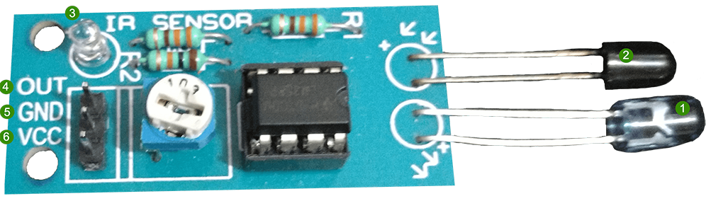
Components: IR Sensor
- Emitter: This component continuously emits the infrared signal
- Receiver: It waits for the signal which is bounced back by obstacle
- Indicator: On board LED to signal if obstacle is deducted by the sensor
- Output: Could be used as Input for further processing of the signal
- Ground: Ground/Negative point of the circuit
- Voltage: Input 3.3V
Objective: Detecting obstacle with IR Infrared Sensor
In this tutorial we will be creating a circuit using following components to detect obstacle.
- Raspberry Pi 3
- IR (Infrared) Sensor
- 1 LED
- 1 Resistor (330 Ω)
- Few jumper cables
- 1 Breadboard
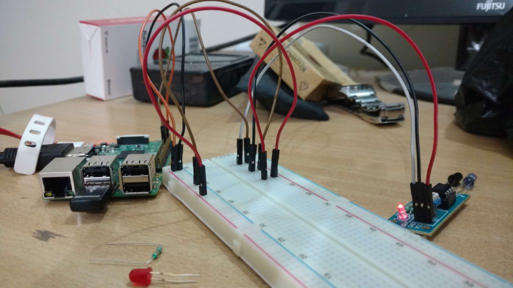
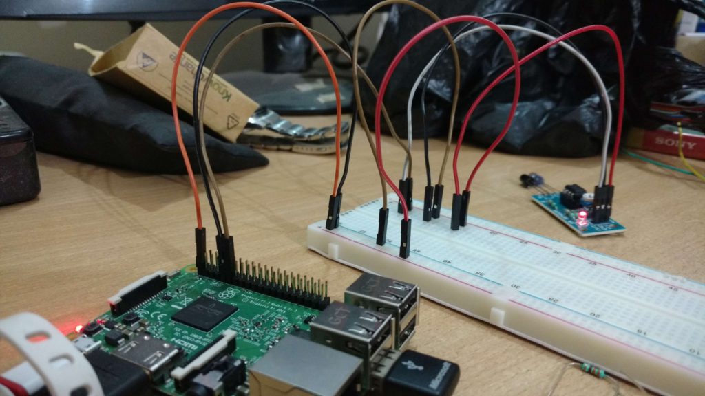
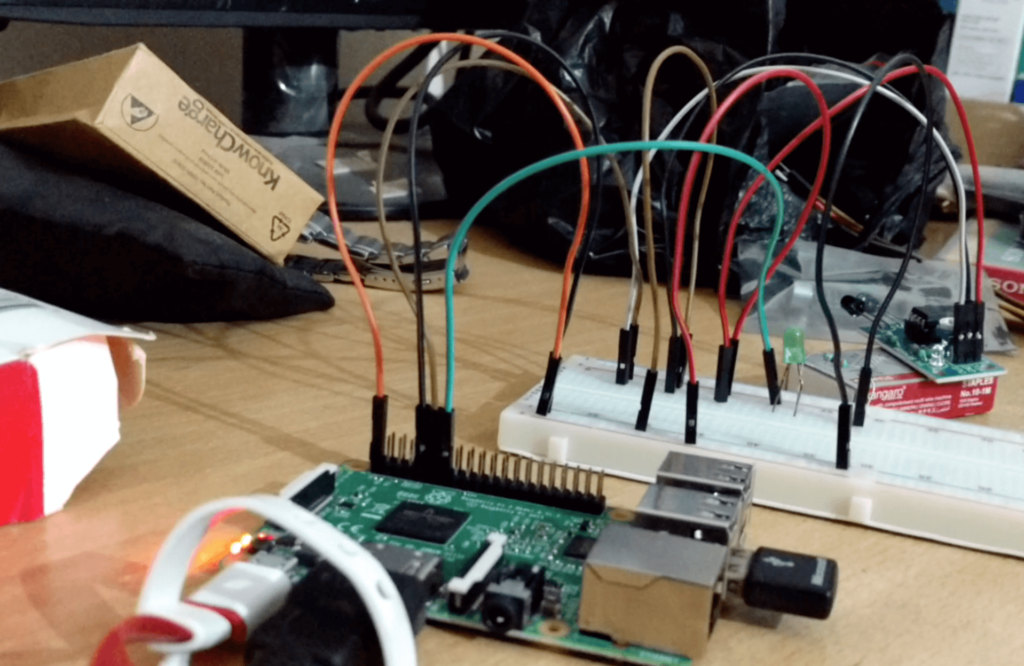
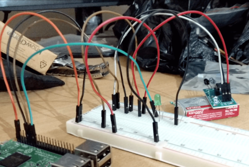
Circuit: To detect obstacles
We will be creating a circuit which will turn on the LED when an obstacle is detected. And, as soon as the obstacle is removed from the way the LED will turn off. In order to achieve that follow the steps to create required circuit.
Part 1: Connecting IR Sensor
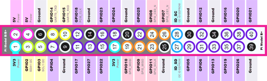
IR Sensor has 3 pins, viz VCC, GND and OUT. We will use GPIO 17 (do not get confused with pin number 17) for receiving input from the sensor.
- Connect GPIO 17 from the Raspberry Pi to Breadboard (5a)
- Connect OUT pin of the sensor with the Breadboard (5c)
This will send input received from sensor to GPIO 17, which will be processed further. - Connect GND (any pin from board will work, in this post we are using pin number 9) with negative line on left side of the breadboard
- Connect GND of the IR Sensor to Breadboard (10c)
- Connect GND from Step 3 to Breadboard (10a)
- Connect VCC of the IR Sensor to Breadboard (15c)
- Connect 3v3 (Pin #1) to positive line on left side of the breadboard
- Connect 3v3 (connected in Step 7) to the Breadboard (15a)
Now the circuit is complete and sensor will detect the obstacle. It can be tested by putting anything in front of the IR Sensor. On-board LED will be on if obstacle is put in front of the sensor, else it will be off.
Part 2: Connecting LED
Objective is to turn on the LED when obstacle is detected.
- Connect GPIO 4 from the board to the Breadboard(20a)
- Connect positive point of the LED (longer pin of the LED) to the Breadboard (20c)
- Connect negative point of the LED (smaller pin of the LED) to the Breadboard (22c)
- Use resistor (330 Ω) to connect negative (row from Part 1: Step 3) to the negative point of the LED(22a)
Now we are ready to send signal based on the input received from IR Sensor to turn on/off the LED.
Part 3: Code to Connect IR Sensor I/P with LED status
from gpiozero import LED
from signal import pause
import RPi.GPIO as GPIO
import time

GPIO.setmode(GPIO.BCM)

LED_PIN = 27
IR_PIN = 17

indicator = LED(LED_PIN)
GPIO.setup(IR_PIN, GPIO.IN)

count = 1

while True:
  got_something = GPIO.input(IR_PIN)
  if got_something:
    indicator.on()
    print("{:>3} Got something".format(count))
  else:
    indicator.off()
    print("{:>3} Nothing detected".format(count))
  count += 1
  time.sleep(0.2)
Save it by name ir_obstacle.py. Code could be found on GitHub.
Part 4: Executing the code
- Open terminal (On Pi itself or login through SSH login)
- Navigate to the directory where the above code is saved
- Type $ python3 ir_obstacle.py and press <enter>
On terminal it will start printing the status based on the conditions.